Language(ZH)
LRHQ131X-02ATL
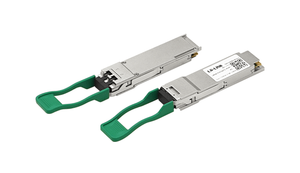
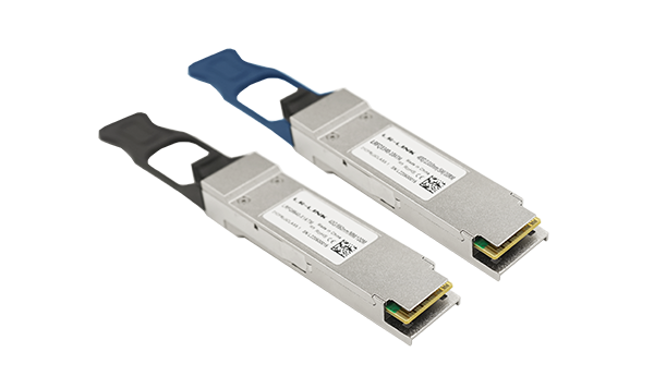
QSFP28 | 100G | Single-mode | 2km
LRHQ131X-02ATL
100G QSFP28 Single-mode Fiber Optical Transceiver
High density interconnectivity;
Supports 100Gb/s data rate links up to 2km on a Single-mode Fiber (SMF) ;
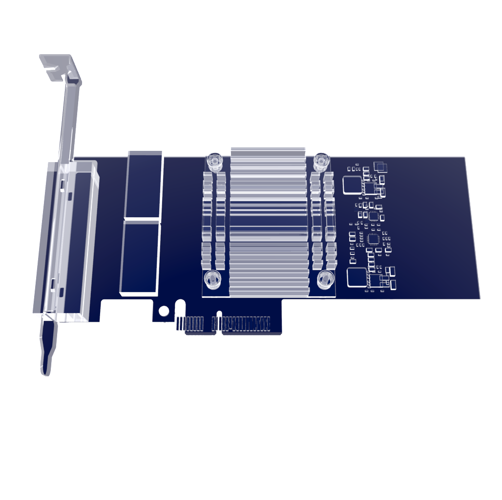
Industry standard QSFP28 form factor ;
Power Dissipation < 3.5W;
Single 3.3V Power Supply ;
ROHS Compliant.;
LR-LINK LRHQ131X-02ATL links from 2m to 2km over a standard SMF.QSFP28 footprint (Quad Small Form-factor Pluggable) with 2 unidirectional LC SMF optical connector receptacles. Compliant to the SFF-8665 Pluggable Transceiver Solution (QSFP28) MSA. Electrical Interface based on CAUI-4 as defined by IEEE 802.3 CL83E. Compliant to the SFF-8636 Common Management Interface MSA. 38 pin hot pluggable edge connector electrical interface .The transmitter consists of a retimed quad input, 4 un-cooled CWDM DFB lasers operating on the ITU G.694.2 wavelength grid at 1271, 1291, 1311 and 1331nm and multiplexed into a single SMF output.The receiver consists of a CWDM de-multiplexer, a quad photodiode receiver and a retimed electrical output .Provides Bias and Transmit Power Monitoring (TPM) for each of the 4 transmitter channels.Provides RSSI Monitoring for each of the 4 receiver channels. Provides monitoring of the voltage supplies and case temperature.Provides Module Present and Interrupt signals Input control pins for Module Select, Module Reset and Low Power Modes. Supports operation for a case temperature of 0°C to +70°C.Includes customized coding option for module security implementation.
Absolute Maximum Ratings | |||||
Parameter | Symbol | Min. | Typical | Max. | Unit |
Storage Temperature Range | TS | -40 | - | +85 | °C |
Supply Voltage | VCC | 0 | - | 4 | V |
Relative Humidity(non-condensing) | RH | 10 | - | 90 | % |
Recommended Operating Conditions | |||||
Parameter | Symbol | Min. | Typical | Max. | Unit |
Case Temperature - Operating | TCASE | 0 | - | 70 | °C |
Supply Voltage | VCC | 3.14 | - | 3.46 | V |
Power Consumption | PDISS | - | - | 3.5 | W |
Power Consumption-LP Mode | PDISS-LP | - | - | 1.5 | W |
Transmitter | |||||
Parameter | Symbol | Min. | Typical | Max. | Unit |
Signaling Rate, R each lane | 25.78125 100 ppm | Gb/s | |||
Lane Wavelength Range | L0 | 1264.5 | 1271 | 1277.5 | nm |
L1 | 1284.5 | 1291 | 1297.5 | nm | |
L2 | 1304.5 | 1311 | 1317.5 | nm | |
L3 | 1324.5 | 1331 | 1337.5 | nm | |
Average Optical Power per lane | - | -6.5 | - | 2.5 | dBm |
Total Average Launch Power | - | - | 8.5 | dBm | |
Optical Modulation Amplitude(OMA), each lane | - | -4 | - | 2.5 | dBm |
Launch Power in OMA minus TDP, each lane | - | -5 | - | - | dBm |
Transmitter and Dispersion Penalty(TDP) each lane | - | - | - | 3 | dB |
Average Launch Power per Lane @ TX Off State | - | - | - | -30 | dBm |
Extinction Ratio | - | 3.5 | - | - | dB |
Relative Intensity Noise (OMA) | - | - | - | -130 | dB/KZ |
Side-Mode Suppression Ration (SMSR) | - | 30 | - | - | dB |
Optical Return Loss Tolerance | - | - | - | 20 | dB |
Transmitter Reflectance | - | - | - | -12 | dB |
Transmitter Output Power Monitoring Accuracy | - | -3 | - | 3 | dB |
Transmitter eye mask definition {X1, X2, X3, Y1, Y2, Y3} | - | {0.31,0.4,0.45,0.34,0.38,0. 4} | - | ||
Receiver | |||||
Parameter | Symbol | Min. | Typical | Max. | Unit |
Signaling Rate, R each lane | - | 25.78125 100 ppm | Gb/s | ||
Lane Wavelength Range | L0 | 1264.5 | 1271 | 1277.5 | nm |
L1 | 1284.5 | 1291 | 1297.5 | nm | |
L2 | 1304.5 | 1311 | 1317.5 | nm | |
L3 | 1324.5 | 1331 | 1337.5 | nm | |
Damage Threshold | - | 3.5 | - | - | dBm |
Average Receive Power, each lane | - | -11.5 | - | 2.5 | dBm |
Receiver Power (OMA), each Lane | - | - | - | 2.5 | dBm |
Receiver Reflectance | - | - | - | -26.0 | dB |
Receiver Sensitivity (OMA) per lane | - | - | - | -10.0 | dBm |
RSSI Accuracy | - | -3 | - | 3 | dB |
Where to Buy

+86 4000 588 108
service@lr-link.com
Copyright © 2024 Linkreal Co., Ltd. All Rights Reserved.
+86 4000 588 108