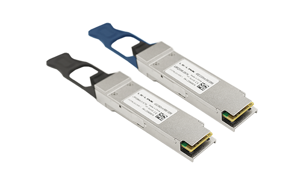
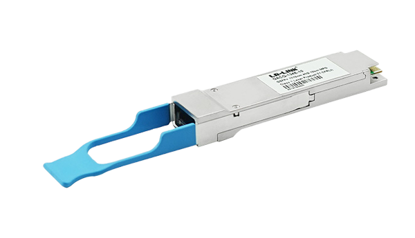
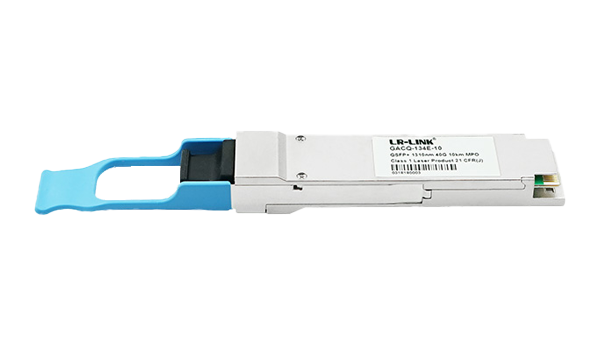
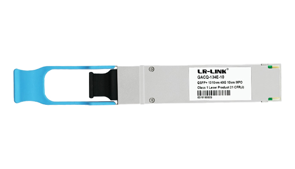
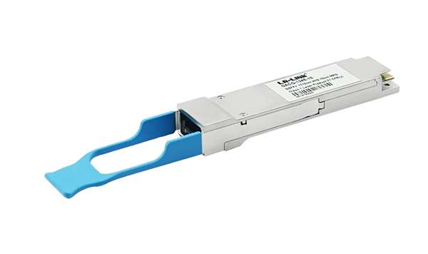
LR-LINK LRFQ1340-X10ATM is a high performance, low power consumption, long reach interconnect solution supporting 40G Ethernet, fiber channel and PCIe. It is compliant with the QSFP MSA and IEEE 802.3ae 10GBASE-LR/LW3. QSFP PSM LR4 is an assembly of 4 full-duplex lanes, where each lane is capable of transmitting data at rates up to 10.3125Gb/s, providing an aggregated rate of 40Gb/s.
Absolute Maximum Ratings | |||||
Parameter | Symbol | Min. | Typical | Max. | Unit |
Supply Voltage | Vcc | -0.3 | - | 3.6 | V |
Input Voltage | Vin | -0.3 | - | Vcc+0.3 | V |
Storage Temperature | Ts | -20 | - | 85 | ºC |
Case Operating Temperature | Tc | 0 | - | 70 | ºC |
Humidity(non_condensing) | Rh | 5 | - | 95 | % |
Recommended Operating Conditions | |||||
Parameter | Symbol | Min. | Typical | Max. | Unit |
Supply Voltage | Vcc | 3.13 | 3.3 | 3.47 | V |
Operating Case Temperature | Tc | 0 | - | 70 | ºC |
Data Rate Per Lane | fd | - | 10.3125 | - | Gb/s |
Humidity | Rh | 5 | - | 85 | % |
Power Dissipation | Pm | - | - | 2 5 | W |
Fiber Bend Radius | Rb | 3 | - | - | cm |
Transmitter | |||||
Parameter | Symbol | Min. | Typical | Max. | Unit |
Lane Wavelength Range | λc | 1290 | 1310 | 1330 | nm |
SMSR | σ | 30 | - | - | dB |
Average Launch Power (each lane) | Pout | -8.2 | - | 0.5 | dBm |
Optical Modulation Amplitude (each lane) | OMA | -5.2 | - | 3.0 | dBm |
Transmitter and dispersion penalty (TDP), each lane | TDP | - | - | 2.6 | dB |
Extinction Ratio | ER | 3.5 | - | dB | |
Average Launch Power of OFF Transmitter (each lane) | Poff | - | - | -30 | dB |
Eye Mask Coordinates :X1, X2, X3, Y1, Y2, Y3 | {0.25, 0.4, 0.45, 0.25, 0.28, 0.4} | ||||
Receiver | |||||
Parameter | Symbol | Min. | Typical | Max. | Unit |
Lane Wavelength Range | λc | 1260 | 1310 | 1355 | nm |
Receiver sensitivity in OMA, each lane | - | - | - | - 12.6 | dBm |
Stressed Receiver Sensitivity in OMA | - | - | - | -10.3 | dBm |
Average Power at Receiver | - | - 13.7 | - | 2.3 | dBm |
Receiver Reflectance | RR | - | - | -26 | dB |
LOS Assert | LOSA | -30 | - | - | dBm |
LOS De-Assert | LOSD | - | - | - 14 | dBm |
LOS Hysteresis | LOSH | 0.5 | - | - | dB |
Parameter | Symbol | Min. | Typical | Max. | Unit |
Differential Input Impedance | Zin | 90 | 100 | 110 | ohm |
Differential Output Impedance | Zout | 90 | 100 | 110 | ohm |
Differential Input Voltage Amplitude1 | ΔVin | 120 | - | 1200 | mVp-p |
Differential Output Voltage Amplitude2 | ΔVout | 300 | - | 850 | mVp-p |
Skew | Sw | - | - | 300 | ps |
Bit Error Rate | BER | - | 1×10- 12 | - | - |
Input Logic Level High | VIH | 2.0 | - | Vcc | V |
Input Logic Level Low | VIL | 0 | - | 0.8 | V |
Output Logic Level High | VOH | Vcc-0.5 | - | Vcc | V |
Output Logic Level Low | VOL | 0 | - | 0.4 | V |