Language(ZH)
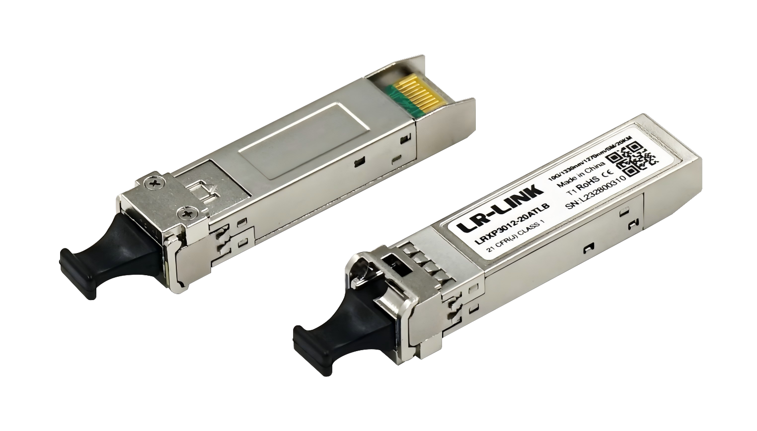
LRXP3012-20ATLB
LRXP3012-20ATLB
10G SFP+ Single-Mode Single-Fiber Ethernet Fiber Module
Single power supply + 3.3V supply and LC interface;
Hot-swappable design;
Up to 10Gb/s transmit data transfer capability;
1330nm DFB laser transmitter;
1270nm PIN receiver;
RoHS compliant;
Transmission distance up to 20km on single mode single fiber;
Operating temperature range: 0℃~70℃ .
Technical parameter
Absolute Maximum Ratings | |||||
Parameter | Symbol | Min. | Typical | Max. | Unit |
Data rate | DR | 9.98 | 10 | 11.3 | Gb/s |
Operating temperature | TC | 0 | 70 | ◦C | |
Storage temperature | TSTO | -40 | 85 | ◦C | |
Operating voltage | VCC | 3.14 | 3.3 | 3.46 | V |
Optical Characteristics
Transmitter | |||||
Parameter | Symbol | Min. | Typical | Max. | Unit |
Transmitted optical power | P | -8.2 | 0.5 | dBm | |
Optical center wavelength | λC | 1320 | 1330 | 1340 | nm |
Extinction Ratio | ER | 3.5 | dB | ||
Receivers | |||||
Parameter | Symbol | Min. | Typical | Max. | Unit |
Input optical power overload | PIN | 0.5 | 0 | dBm | |
Optical center wavelength | λC | 1260 | 1270 | 1280 | nm |
LOS High Level Warning | LOSA | -30 | dBm | ||
LOS Low Level Warning | LOSD | -17 | dBm | ||
Dispersion Penalty | 0.5 | dB | |||
SFP+ Module Pad Layout
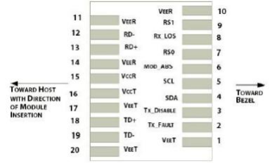
SFP+ Pin Definitions
Pin | Name | Function/Description |
1 | VeeT | Transmitter Ground |
2 | Tx_Fault | Transmitter Fault - High indicates a fault condition |
3 | Tx_Disable | Transmitter Disable – High or open disables the transmitter |
4 | SDA | Two wire serial interface Data Line |
5 | SCL | Two wire serial interface Clock Line |
6 | MOD_ABS | Module Absent (Output), connected to VeeT or VeeR in the module |
7 | RS0 | Rx Rate Select,not used |
8 | RX_LOS | Loss of Signal indication. Logic 0 indicates normal operation |
9 | RS1 | Tx Rate Select,not used |
10 | VeeR | Receiver Ground |
11 | VeeR | Receiver Ground |
12 | RD- | Receiver Inverted DATA out |
13 | RD+ | Receiver Non-inverted DATA out |
14 | VeeR | Receiver Ground |
15 | VccR | Receiver Power Supply |
16 | VccT | Transmitter Power Supply |
17 | VeeT | Transmitter Ground |
18 | TD+ | Transmitter Non-Inverted DATA in |
19 | TD- | Transmitter Inverted DATA in |
20 | VeeT | Transmitter Ground |
Where to Buy

+86 4000 588 108
service@lr-link.com
Copyright © 2024 Linkreal Co., Ltd. All Rights Reserved.
+86 4000 588 108