
Language(ZH)
LRXP8510-X3ATL(10/1G)
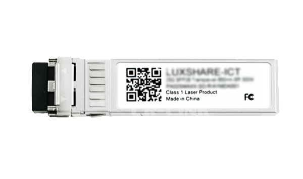
1/ 10Gb/s SFP+ LR 20 KM Optical Transceiver Module
LRXP8510-X3ATL(10/1G)
1/ 10Gb/s SFP+ LR 20 KM Optical Transceiver Module
Supported Rates: 1.25 Gb/s or 9.83 Gb/s to 11.3 Gb/s
Compliant with IEEE 802.3ae 10 GBASE-LR/LW and 1000BASE-LX standards Compliant with SFF-8431 standard
Hot-swappable design
1310 nm DFB laser transmitter
Dual LC interfaces
Digital Diagnostic Functionality
Up to 20 km transmission distance over single-mode fiber Single 3.3V power supply
RoHS compliant
Operating Temperature Range (Case Temperature): Commercial Temperature Grade: 0°C to 70°C
The LRXP8510-X3ATL(10/1G)(T1) SFP+ optical transceiver module is based on the 10G Ethernet IEEE 802.3ae standard and SFF-8431 standard, providing a fast and reliable interface for 10G Ethernet applications. This product implements digital diagnostic functions via a 2-wire serial bus and complies with the SFF-8472 standard.
Applications
10GBASE-LR/LW 10G Ethernet
1000BASE-LX 1G Ethernet
Ordering Information
Model | Description |
LRXP8510-X3ATL(10/1G)(T1) | 1000BASE-LX and 10 GBASE-LR SFP+ 1310 nm LC interface Single-mode fiber transmission distance: 20 km Commercial temperature range |
Product Specifications
Parameter | Symbol | Min | Typ. | Max | Unit | Note |
Data rate 1 | DR1 | 1.25 | Gb/s | 1 | ||
Data rate2 | DR2 | 9.83 | 10.3125 | 11.3 | Gb/s | 1 |
Error Bit Rate | BER | 10- 12 | ||||
Operating Temperature | TC | 0 | 70 | 。C | 2 | |
Storage temperature | TSTO | -40 | 85 | 。C | 3 | |
Operating Current | ICC | 290 | 380 | mA | 4 | |
Operating Voltage | VCC | 3.14 | 3.3 | 3.46 | V | |
Maximum Voltage | PC | 1.0 | 1.3 | W | ||
Data rate (RS0=LOW) | V MAX | - 0 . 5 | 4 | V | 4 |
Note:
1. IEEE 802.3ae
2. Enclosure surface temperature
3. Ambient temperature
4. Electrical interface
Transmission distance
Data rate | Fiber Optic Type | Distance Range (km) |
1.25 Gb/s | 9/125 um Single-mode fiber | 20 |
9.83-11.3 Gb/s | 9/125 um Single-mode fiber | 20 |
Optical Characteristics—Transmitter
VCC =3.14V to 3.46V ,TC
Parameter | Symbol | Min | Typ. | Max | Unit | Note |
Transmit optical power @ 1.25Gb/s | PTX1 | -9 . 5 | -3 | dBm | 1 | |
Transmit optical power @ 10.3Gb/s | PTX2 | -8 . 2 | 0.5 | dBm | 1 | |
Optical center wavelength | λC | 1260 | 1355 | nm | ||
Optical modulation amplitude | OMA | -5 . 2 | dBm | 2 | ||
Extinction ratio @ 1.25Gb/s | ER1 | 9 | dB | |||
Extinction ratio @ 10.3 Gb/s | ER2 | 3.5 | dB | |||
Spectral width (-20 dB) | Δλ | 1 | nm | |||
Side-mode suppression ratio | SMSR | 30 | dB | |||
Relative intensity noise | RIN | - 128 | dB/Hz | |||
Transmitter dispersion cost | TDP | 3.2 | dB | |||
Output optical power when transmitter is off | POUT_OFF | -30 | dBm | 1 | ||
Jitter | 2 |
Note:
1. Average optical power
2. Compliant with IEEE 802.3ae standard
Optical Characteristics—Receiver
VCC = 3.14V to 3.46V, TC
Parameter | Symbol | Min | Typ. | Max | Unit | Note |
Optical Center Wavelength | λC | 1260 | 1600 | nm | ||
Receiver Overload | POL | 0.5 | dBm | |||
Receiver Sensitivity @ 1.25Gb/s | RX_SEN1 | - 19 | dBm | 1 | ||
Receiver Sensitivity @ 10.3Gb/s | RX_SEN2 | - 14 .4 | dBm | 2 | ||
Receiver Reflectivity | TRRX | - 12 | dB | |||
LOS Signal Active @ 1.25Gb/s | LOSA | -30 | dBm | |||
LOS Signal Active @ 10.3Gb/s | LOSA | -30 | dBm | |||
LOS Signal Loss @ 1.25Gb/s | LOSD | - 1 7 | dBm | |||
LOS Signal Loss @ 10.3Gb/s | LOSD | - 1 7 | dBm | |||
LOS Signal Latency Range | LOSH | 0.5 | dB |
Note:
1. Average optical power measured using the minimum ER value within the defined range; BER < 10⁻¹²; 27 -1 PRBS
2. Average optical power measured using the minimum ER value within the defined range; BER < 10⁻¹²; 231 -1 PRBS
Electrical Characteristics—Transmitter
VCC =3.14V to 3.46V ,TC
Parameter | Symbol | Min | Typ. | Max | Unit | Note |
Differential Input Impedance | RIN | 100 | Ω | |||
Differential Input Swing | VIN PP | 180 | 700 | mV | ||
Transmitter Shutdown Voltage | VD | 2 | VCC | V | ||
Transmitter Enable Voltage | VEN | VEE | VEE+ 0.8 | V |
Electrical Characteristics—Receiver
VCC = 3.14V to 3.46V, TC
Parameter | Symbol | Min | Typ. | Max | Unit | Note |
Differential Output Swing | VOUT PP | 300 | 850 | mV | ||
Output Signal Rise/Fall Time (20%-80%) | tr/tf | 28 | ps | |||
LOS Signal Active | VLOS A | 2 | VCC HOST | V | ||
LOS Signal Inactive | VLOS D | VEE | VEE +0.5 | V |
DDM Threshold Information
Parameter | Alarm Threshold | Warning Threshold | |||
High Value | Low Value | High Value | Low Value | ||
Temperature( 。 C) | 1G | 90 (5A 00) | -45 (D3 00) | 85 (55 00) | -40 (D8 00) |
10G | 90 (5A 00) | -10 (F6 00) | 85 (55 00) | -5 (FB 00) | |
voltage(V) | 3.63(8D CC) | 2.97 (74 04) | 3.46 (87 28) | 3.13 (7A 44) | |
Electric current( mA ) | 100 (C3 50) | 2 (03 E8) | 80 (9C 40) | 4 (07 D0) | |
Optical power output(dBm) | 1G | -2.2 (17 7E) | -10.5 (03 81) | -3 (13 93) | -9.5 (04 62) |
10G | 1.3 (34 98) | -9.2 (04 BA) | 0.5 (2B D4) | -8.2 (05 E9) | |
Received optical power(dBm) | 1G | 3.0 (4E 20) | -30.4 (00 09) | 0.0 (27 10) | -27.2 (00 13) |
10G | 3.0 (4E 20) | -18.0 (00 9E) | 0.0 (27 10) | -15.0 (01 3C) | |
Pin Definitions
PIN # | Symbol | Instruction | Note |
1 | VEET | Transmit Ground (shared with Receive Ground) | 1 |
2 | TX_ FAULT | Transmit Fault Alarm | |
3 | TX_DISABLE | This signal disables the module's transmitter when high or open-circuited | 2 |
4 | SDA | Two-Wire Serial Interface Data Line | 3 |
5 | SCL | Two-Wire Serial Interface Clock Line | 3 |
6 | MOD ABS | Module Insertion Indicator Pin, internally grounded within the module | 3 |
7 |
RS0 | Module Rate Selection: Open circuit or low level = 1.25 Gb/s rate (low bandwidth) High level = 9.95 - 10.31 Gb/s rate (high bandwidth) | |
8 | LOS | Signal Loss Indicator, Low Level Indicates Module Normal Operation | 4 |
9 | RS1 | Not Connected | |
10 | VEER | Receiver Ground (Shared with Transmitter Ground) | 1 |
11 | VEER | Receiver Ground (Shared with Transmitter Ground) | 1 |
12 | RD– | Receiver Data Output Negative, AC-Coupled | |
13 | RD+ | Receiver Data Output Positive, AC-Coupled | |
14 | VEER | Receiver Ground (Shared with transmitter ground) | 1 |
15 | VCCR | Receiver power supply | |
16 | VCCT | Transmitter power supply | |
17 | VEET | Transmitter ground (Shared with receiver ground) | 1 |
18 | TD + | Transmitter data input positive, AC-coupled | |
19 | TD– | Transmitter data input negative, AC-coupled | |
20 | VEET | Transmitter ground (Shared with receiver ground) | 1 |
Where to Buy

+86 4000 588 108
service@lr-link.com
Copyright © 2024 Linkreal Co., Ltd. All Rights Reserved.
+86 4000 588 108