

Language(ZH)
LRXP1310-20ATL(10/1G)
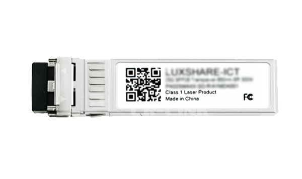
1G/10G SFP+ Short Wavelength (850nm) Optical Transceiver Module
LRXP1310-20ATL(10/1G)
LRXP1310-20ATL(10/1G)
Supports selectable dual-rate operation at 1.25Gb/s or 9.83Gb/s to 11.3Gb/s
Compliant with IEEE 802.3-2012 10GBASE-SR/SW and 1000BASE-SX standards
Meets SFF-8431 specifications
Hot-swappable design
850nm VCSEL laser transmitter
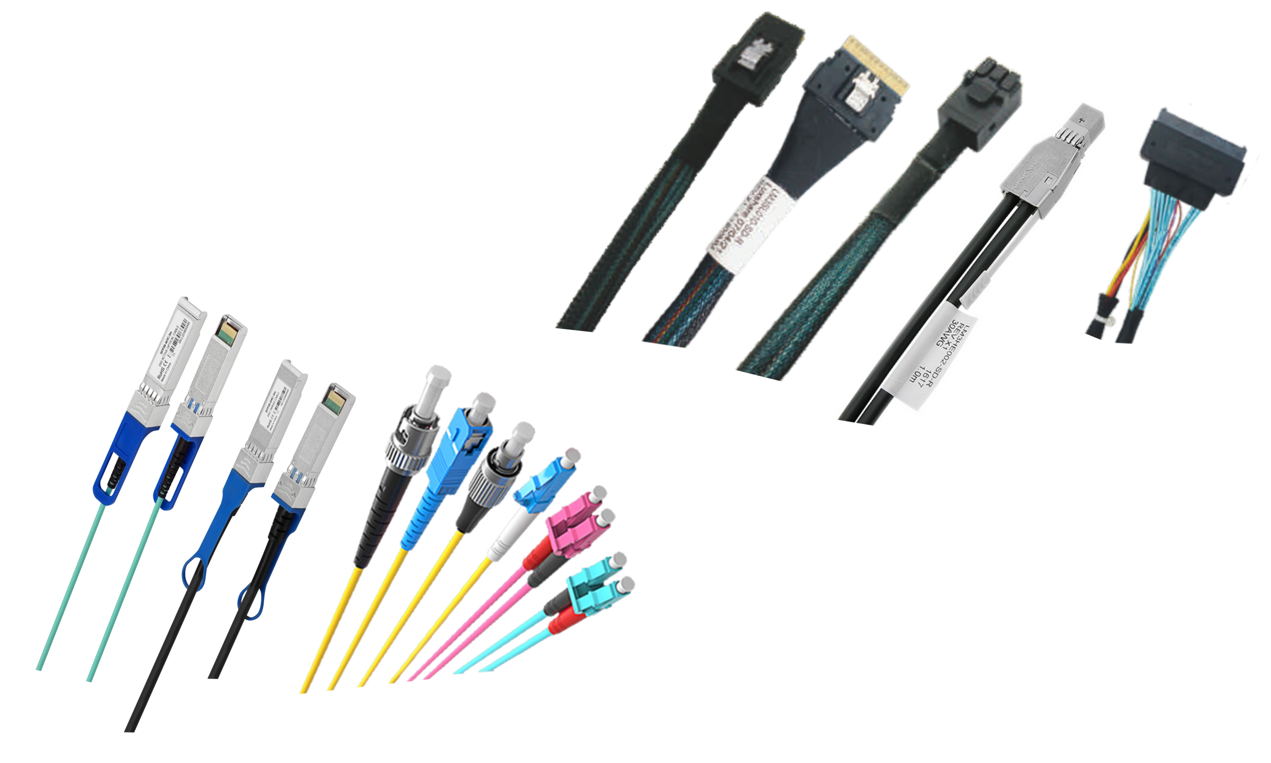
Dual LC interfaces
Digital diagnostics capability
Single 3.3V power supply
RoHS compliant
Class 1 laser product, compliant with EN 60825-1
Operating temperature range (case temperature): 0°C to 70°C
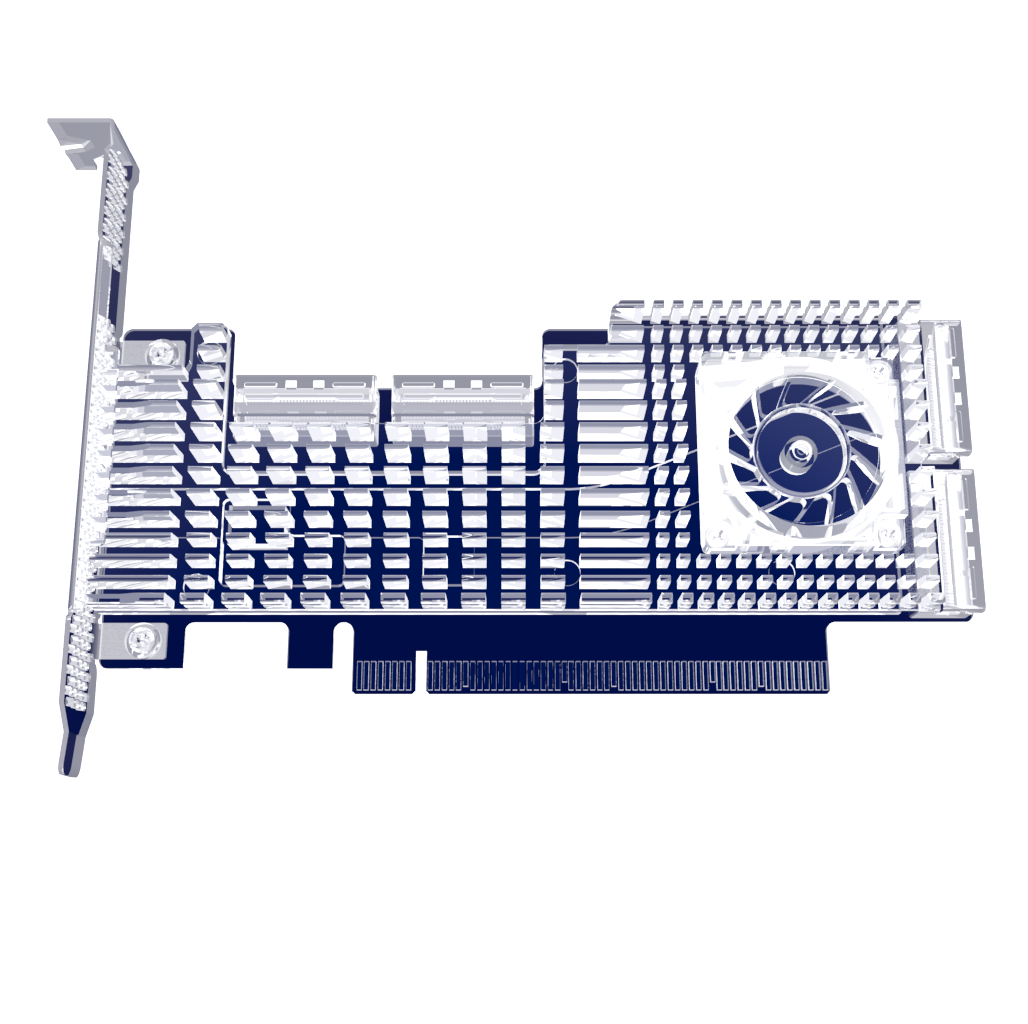
The LRXP1310-20ATL(10/1G) dual-rate SFP+ optical module is based on 10G Ethernet and 1G Ethernet standards, compliant with SFF-8431,IEEE 802.3-2012, 10GBASE-SR/SW, and 1000BASE-SX standards, providing a fast and reliable interface for 10G and 1G Ethernet applications.
This product implements digital diagnostics via a 2-wire serial bus and complies with the SFF-8472 standard.
Applications
• 10GBASE-SR/SW 10G Ethernet
• 1000BASE-SX 1G Ethernet
General Product Specifications
Parameter | Symbol | Min | Typ. | Max | Unit | Note |
Data rate (RS0=LOW) | DR | 1.25 | Gb/s | 1 | ||
Data rate (RS0=HIGH) | DR | 9.83 | 10.3125 | 11.3 | Gb/s | 1 |
Error Bit Rate | BER | 10−12 | ||||
Operating Temperature | TC | 0 | 70 | 。C | 2 | |
Storage temperature |
TSTO | -40 | 85 | 。C | 3 | |
Operating Current |
ICC | 180 | 220 | mA | 4 | |
Operating Voltage | VCC | 3.14 | 3.3 | 3.46 | V | |
Maximum Voltage | VMAX | -0.5 | 4 | V | 4 |
Note:
1. IEEE 802.3-2012
2. Housing temperature
3. Ambient temperature
4. Electrical interface
Fiber Optic Type | Mode bandwidth @850nm (MHz-km) | Distance Range (m) | |
1.25Gb/s | 9.83-11.3Gb/s | ||
62.5/125um Multimode fiber | 160 | 220 | 26 |
62.5/125um Multimode fiber | 200 | 275 | 33 |
50/125um Multimode fiber | 400 | 500 | 66 |
50/125um Multimode fiber | 500 | 550 | 82 |
50/125um Multimode fiber | 2000 | >550 | 300 |
Transmission distance
Optical Characteristics—Transmitter (RS0 = Low 1G Rate Operating Mode)
VCC = 3.14V to 3.46V, TC = 0°C to 70°C
Parameter | Symbol | Min | Typ. | Max | Unit | Note |
Optical power output | PTX | -9.5 | -1 | dBm | 1 | |
Optical Center Wavelength | λC | 840 | 850 | 860 | nm | |
Optical Modul ation Amplitude | OMA | -1.5 | dBm | 2 | ||
Extinction Ratio | ER | 3 | 5.5 | dB | ||
Spectral Width(RMS) | Δλ | 0.45 | nm | |||
Relative Intensity Noise | RIN | -128 | dB/Hz | |||
Transmitter Dispersion Cost | TDP | 3.9 | dB | |||
Jitter | TJ | 3 | ||||
Optical Power Output When Transmitter is Off |
POUT_OFF | -30 | dBm | 4 |
Note:
1. Class 1 laser products
2. IEEE 802.3-2012
3. Compliant with IEEE 802.3-2012 requirements
4. Average optical power
Optical Characteristics—Receiver (RS0 = High 10G rate operating mode)
VCC=3.14V to 3.46V, TC=0。C to 70。C
Parameter | Symbol | Min | Typ. | Max | Unit | Note | |
Center Wavelength | λC | 840 | 860 | nm | |||
Receiver Sensitivity @ 10.3Gb/s | RX_SEN | -10 | dBm | 1 | |||
Receiver Overload | POL | 0.5 | dBm | ||||
Receiver Reflection | TRRX | -12 | dB | ||||
LOS Signal Active | LOSA | -30 | dBm | ||||
LOS Signal Inactive | LOSD | -14 | dBm | ||||
LOS Signal Delay Interval | LOSH | 0.5 | dB |
Note:
1. Tested using the worst extinction ratio; BER < 10^(−12); 231-1 PRBS
Electrical Characteristics—Transmitter
VCC=3.14V to 3.46V, TC=0 。C to 70。C
Parameter | Symbol | Min | Typ. | Max | Unit | Note |
Differential Input Impedance | RIN | 100 | Ω | |||
Differential Input Swing | VIN PP | 180 | 700 | mV | ||
Transmitter Shutdown Voltage | VD | 2 | VCC | V | ||
Transmitter Enable Voltage | VEN | VEE | VEE+0.8 | V |
Electrical Characteristics—Receiver
VCC=3.14V to 3.46V, TC=0。C to 70 。C
Parameter | Symbol | Min | Typ. | Max | Unit | Note |
Differential Output Swing | VOUTPP | 300 | 850 | mV | ||
Output Signal Rise/Fall Time (20%-80%) | tr/tf | 28 | ps | |||
LOS Signal Active | VLOSA | 2 | VCC HOST | V | ||
LOS Signal Inactive | VLOSD | VEE | VEE+0.5 | V |
A0H Register Specifications
IIC Address | Byte size | Register Name | Register Description | Value (HEX) |
0 | 1 | Identifier | SFP+ | 03 |
1 | 1 | Extended Identifier | Utilizes IIC interface | 04 |
2 | 1 | Connector | Features LC connector | 07 |
3-10 | 8 | Transceiver | 10GBase-SR/ 1000BASESX | 10 00 00 01 00 00 00 00 |
11 | 1 | Encoding | Using 64B/66B coding | 06 |
12 | 1 | BR, Nominal | Nominal rate 10.3 Gb/s | 67 |
13 | 1 | Rate Identifier | Rate selection capability | 02 |
14 | 1 | Length(9μm)-km | Transmission distance over single-mode fiber | 00 |
15 | 1 | Length (9μm)-100m | Transmission distance over single-mode fiber | 00 |
16 | 1 | Length (50μm)-10m | Transmission distance over multimode fiber 80m | 08 |
17 | 1 | Length (62.5 μm)-10m | Transmission distance over multimode fiber 20m | 02 |
18 | 1 | Length (Copper) | Transmission distance over copper cable | 00 |
19 | 1 | Length (50μm)-10m | Transmission distance over multimode fiber 300m | 1E |
20-35 | 16 | Vendor name | ModuleTek | ASCII Format |
36 | 1 | Transceiver | Undefined | 00 |
37-39 | 3 | Vendor OUI | No Manufacturer OUI | 00 00 00 |
40-55 | 16 | Vendor PN | Manufacturer Product Model | Manufacturer-defined |
56-59 | 4 | Vendor Revision Number | Manufacturer Product Version Number | Manufacturer-defined |
60-61 | 2 | Wavelength | Laser Wavelength | 03 52 |
62 | 1 | Reserved | Undefined | 00 |
63 | 1 | CC_BASE | 0-62 byte checksum | Manufacturer-defined |
64-65 | 2 | Enhanced Options | 1. Rx_LOS signal monitoring | 00 3A |
66 | 1 | BR, max | 2. Tx_FAULT signal monitoring | 00 |
67 | 1 | BR, min | 3. Tx_DIS signal monitoring | 00 |
68-83 | 16 | Vendor SN | 4. Power Level monitoring | Manufacturer-defined |
84-91 | 8 | Date code | NA | Manufacturer-defined |
92 | 1 | Monitoring Type | NA | 68 |
93 | 1 | Enhanced Options | Manufacturer serial number | F0 |
94 | 1 | Compliance | Date code | 08 |
95 | 1 | CC_EXT | DOM information internal calibration | Manufacturer-defined |
96-127 | 32 | Vendor Specific | Received optical power measurement using average optical power | Manufacturer-defined |
128-255 | 128 | Vendor Specific | 1. Transmitted and received optical power Alarm and Warning monitoring | Manufacturer-defined |
Digital Diagnostic Function
The LRXP1310-20ATL(10/1G) supports the 2-wire serial communication protocol defined in SFF-8472. This product accesses digital diagnostic information through a 2-wire interface at address 0xA2. Digital diagnostics default to internal calibration. The internal microcontroller unit continuously monitors device operating parameters in real time, including transceiver temperature, laser bias current, transmit optical power, receive optical power, and transceiver supply voltage. The module implements SFF-8472 alarm functionality, alerting users when specific operating parameters exceed factory-set normal ranges.
10GBASE-SR Mode Digital Diagnostic Threshold
Parameters | Alarm Threshold | Alarm Threshold | ||
High Value | Low Value | High Value | Low Value | |
Temperature (°C) | 90 (5A 00) | -10 (F6 00) | 85 (55 00) | -5 (FB 00) |
Voltage (V) | 3.63(8D CC) | 2.97 (74 04) | 3.46 (87 28) | 3.13 (7A 44) |
Current (mA) | 15 ( 1D 4C) | 1 (01 F4) | 12 ( 17 70) | 2 (03 E8) |
Transmit Optical Power (dBm) | 0.79 (2E E0) | -7.97 (06 3C) | 0.0 (27 10) | -7.0 (07 CB) |
Receive Optical Power (dBm) | 3.01 (4E 20) | -16.02 (00 FA) | 0.0 (27 10) | -13.0 (01 F5) |
1000BASE-SX Mode Digital Diagnostic Threshold
Parameters | Alarm Threshold | Alarm Threshold | ||||
High Value | Low Value | High Value | Low Value | |||
Temperature (°C) | 90 (5A 00) | -45 (D3 00) | 85 (55 00) | -40 (D8 00) | ||
Voltage (V) | 3.63(8D CC) | 2.97 (74 04) | 3.46 (87 28) | 3.13 (7A 44) | ||
Current (mA) | 15 ( 1D 4C) | 1 (01 F4) | 12 ( 17 70) | 2 (03 E8) | ||
Transmit Optical Power (dBm) | -2.71 ( 14 F0) | -9.97 (03 EF) | -3.50 ( 11 72) | -9.00 (04 EA) | ||
Receive Optical Power (dBm) | 3.01 (4E 20) | -27.96 (00 10) | 0.00 (27 10) | -23.01 (00 32) | ||
Pin Definitions
PIN # | Symbol | Description | Notes |
1 | VEET | Transmit Ground (shared with Receive Ground) | 1 |
2 | TX_FAULT | Transmit Fault Alarm | |
3 | TX_DISABLE | Disables module transmitter when high or open-circuit | 2 |
4 | SDA | Two-Wire Serial Interface Data Line | 3 |
5 | SCL | Two-Wire Serial Interface Clock Line | 3 |
6 | MOD ABS | Module Insertion Indicator Pin, grounded internally | 3 |
7 | RS0 | Speed Selection | |
8 | LOS | Signal Loss Indicator, low level indicates module operational | 4 |
9 | RS1 | Not Connected | |
10 | VEER | Receive Ground (shared with Transmit Ground) | 1 |
11 | VEER | Receive Ground (shared with transmit ground) | 1 |
12 | RD– | Receive Data Output Negative, AC-coupled | |
13 | RD+ | Receive Data Output Positive, AC-coupled | |
14 | VEER | Receive Ground (shared with transmit ground) | 1 |
15 |
VCCR | Receive Power Supply | |
16 |
VCCT | Transmit Power Supply | |
17 | VEET | Transmit Ground (shared with receive ground) | 1 |
18 | TD+ | Transmitter Data Input Positive, AC-coupled | |
19 | TD– | Transmitter Data Input Negative, AC-coupled | |
20 | VEET | Transmitter Ground (shared with Receiver Ground) | 1 |
Where to Buy

+86 4000 588 108
service@lr-link.com
Copyright © 2024 Linkreal Co., Ltd. All Rights Reserved.
+86 4000 588 108