Language(ZH)
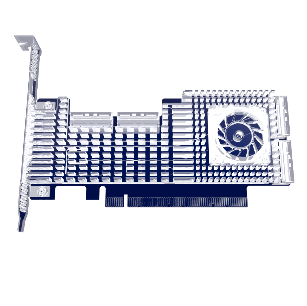
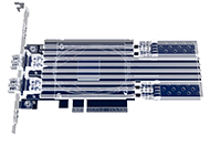
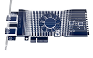
LRTP8525-X1ATL(10/25G)
LRTP8525-X1ATL(10/25G)
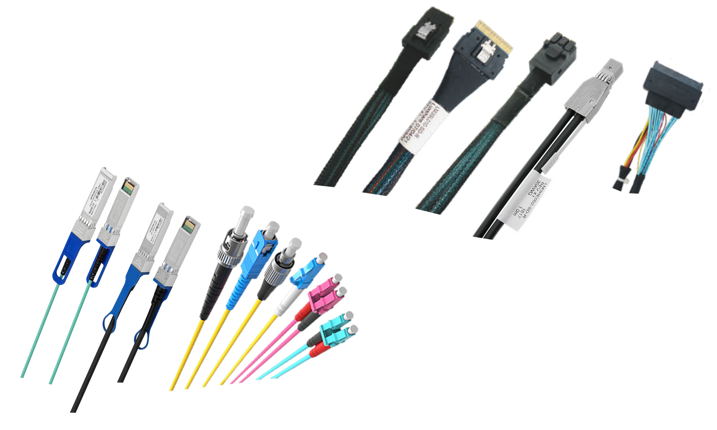
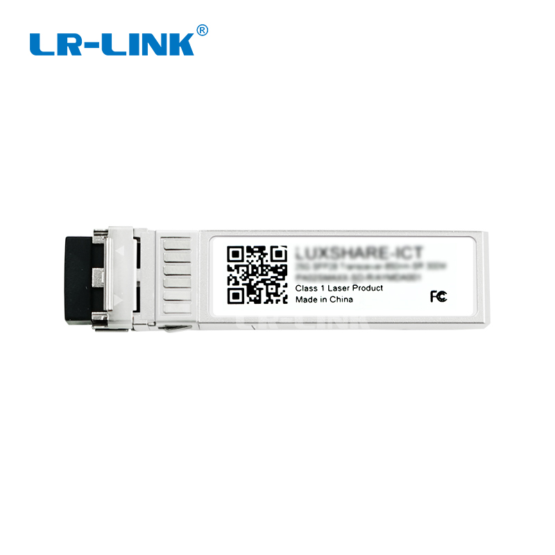
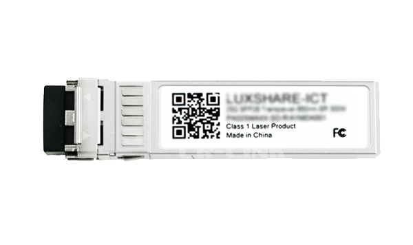
10/25GBASE-SR SFP28 Dual-rate 850nm 100m DOM Duplex LC/UPC MMF Optical Transceiver Module
Up to 25.78 Gb/s bi-directional data links
Duplex LC optical connector
SFP28 MSA compliant
SFF-8431 compliant
Hot-pluggable SFP footprint
Built-in digital diagnostic functions
Capable of over 100m transmission on OM4 multi-mode fiber
Single +3.3V power supply
Operating case temperature: 0 ~70C
Low power consumption < 1.1W
lRoHS-6 compliant
Features:
Up to 25.78 Gb/s bi-directional data links
Duplex LC optical connector
SFP28 MSA compliant
SFF-8431 compliant
Hot-pluggable SFP footprint
Built-in digital diagnostic functions
Capable of over 100m transmission on OM4 multi-mode fiber
Single +3.3V power supply
Operating case temperature: 0 ~70C
Low power consumption < 1.1W
RoHS-6 compliant
Applications:
25GBASE-SR Ethernet
Ordering information
Part No. | Data Rate | Laser | Fiber Type | Distance*Note1 | Optical Interface | Temp. *Note2 | DDMI |
LRTP8525-X1ATL(25/10G) | 25Gbps | 850nm-VCSEL | MMF | 100M | LC | ST | Y |
Note1: 100m with 50/125µm OM4 MMF
Note2: ST: -5 ~ +70 deg C
Regulatory Compliance
Feature | Standard | Performance |
Electrostatic Discharge (ESD) to the Electrical Pins | MIL-STD-883G | HBM class 1, 1000volts and above, |
Method 3015.7 | Contact discharge on Golden Finger. | |
Electrostatic Discharge to the enclosure | IEC-61000-4-2 | Compliant with standards. |
GR-1089-CORE | ||
Electromagnetic Interference (EMI) | FCC Part 15 Class B EN55022:2006 | Compliant with standards Noise |
VCCI Class B | ||
Immunity | IEC 61000-4-3 | Compliant with standards. |
Laser Eye Safety | FDA 21CFR 1040.10 and 1040.11 EN (IEC) 60825-1:2007 | CDRH compliant and Class I laser product. |
EN (IEC) 60825-2:2004+A1 | ||
Component Recognition | UL and CUL | Compliant with standards. |
EN60950-1:2006 | ||
RoHS6 | 2002/95/EC 4.1&4.2 2005/747/EC 5&7&13 | Compliant with standards*note3 |
Note3: In light of item 5 in RoHS exemption list of RoHS Directive 2002/95/EC, Item 5: Lead in glass of cathode ray tubes, electronic components and fluorescent tubes. | ||
In light of item 13 in RoHS exemption list of RoHS Directive 2005/747/EC, Item 13: Lead and cadmium in optical and filter glass. The three exemptions are being concerned for Trixon transceivers, because Trixon transceivers use glass, which may contain Pb, for components such as lenses, windows, isolators, and other electronic components. | ||
Absolute Maximum Ratings*Note4 | ||
Parameter | Symbol | Min | Max | Unit |
Storage Temperature | Tst | -20 | 85 | degC |
Relative Humidity (non-condensation) | RH | - | 85 | % |
Supply Voltage | VCC | -0.5 | 3.6 | V |
Voltage on LVTTL Input | Vilvttl | -0.5 | VCC+0.5 | V |
LVTTL Output Current | Lolvttl | - | 15 | mA |
Voltage on Open Collector Output | Voco | 0 | 6 | V |
Note4: Exceeding any one of these values may destroy the device permanently.
Product Description
The LRTP8525-X1ATL(25/10G) is an 850 nm VCSEL 25Gigabit SFP28 transceiver. It is designed to transmit and receive optical data over 50/125μm multimode optical fiber ( MMF) and support up to 70m on OM3 MMF and 100m on OM4 MMF. The module has a duplex LC optical interface and all mechanical
characteristics are compliant with the current SFP+ specification (SFF-8431 and SFF-8432).
Recommended Operating Conditions
Parameter | Symbol | Min | Typical | Max | Unit |
Operating Case Temperature | Topc | 0 | - | 70 | ℃ |
Power Supply Voltage | VCC | 3.1 | - | 3.5 | V |
Operating Relative Humidity | OH | 5 | - | 85 | % |
Supply Current | Is | - | - | 330 | mA |
Fiber Length: 2000 MHz∙km 50μm MMF (OM3) | 0.5 | 70 | m | ||
- | |||||
Fiber Length: 4700 MHz∙km 50μm MMF (OM4) | 0.5 | 100 | m | ||
- |
Performance Specifications – Electrical
Parameter | Symbol | Min | Typ. | Max | Unit |
Data Rate, each Lane | 25.78 | Gbps | |||
Control I/O Voltage, High | VI H | 2 | - | VCC | V |
Control I/O Voltage, Low | VIL | 0 | - | 0.8 | V |
Tx Input Diff Voltage | VI | 180 | - | 700 | mV |
Tx Input Diff Impedance | Z IN | 90 | 100 | 110 | Ω |
Rx Output Diff Voltage | Vo | 300 | 900 | mV | |
Rx Output Diff Impedance | ZOUT | 90 | 100 | 110 | Ω |
Performance Specifications – Optical
Parameter | Symbol | Min | Typ. | Max | Unit |
Transmitter
Center Wavelength | λt | 840 | 850 | 860 | nm |
RMS Spectral Width | δλt | - | - | 0.6 | nm |
Average Optical Power, each Lane | Pavg | -8.4 | - | +2.4 | dBm |
TDP | - | - | 4.3 | dB | |
Extinction Ratio | ER | 2 | - | - | dB |
Average Launch Power OFF Transmitter, each Lane | Poff | -30 | dBm | ||
- | - |
Receiver
Center Wavelength | Λr | 830 | 850 | 860 | nm |
Rx Sensitivity Note 5 | - | -10.3 | dBm | ||
Receiver Reflectance | - | - | -12 | dB | |
LOS De-Assert | LOSD | -13 | dBm | ||
LOS Assert | LOSA | -30 | dBm | ||
LOS Hysteresis | LOSH | 0.5 | dB |
Note5: Measured with a test pattern, @25.78Gb/s, BER<5E-5. Informative Only
Pin Descriptions
Pin Function Definitions
PinNum.Name | Function | PlugSeq. | Notes |
1 VeeT | Transmitter Ground | 1 | Note 10 |
2 TX Fault | Transmitter Fault Indication | 3 | Note 6 |
3 TX Disable | Transmitter Disable | 3 | Note 7, Module disables on high or open. |
4 SDA | Module Definition 2 | 3 | 2-wire Serial Interface Data Line. |
5 SCL | Module Definition 1 | 3 | 2-wire Serial Interface Clock. |
6 MOD-ABS | Module Definition 0 | 3 | Note 8 |
7 RS0 | RX Rate Select (LVTTL). | 3 | Rate Select 0, optionally controls SFP+ module receiver. This pin is pulled low to VeeT with a >30K resistor.. |
8 LOS | Loss of Signal | 3 | Note9 |
9 RS1 | TX Rate Select (LVTTL). | 1 | Rate Select 1, optionally controls SFP+ |
module transmitter. This pin is pulled low to VeeT with a >30K resistor | |||
10 VeeR | Receiver Ground | 1 | Note 10 |
11 VeeR | Receiver Ground | 1 | Note 10 |
12 RD- | Inv. Received Data Out | 3 | Note 11 |
13 RD+ | Received Data Out | 3 | Note 11 |
14 VeeR | Receiver Ground | 1 | Note 10 |
15 VccR | Receiver Power | 2 | 3.3V ± 5%, Note 12 |
16 VccT | Transmitter Power | 2 | 3.3V ± 5%, Note 12 |
17 VeeT | Transmitter Ground | 1 | Note 10 |
18 TD+ | Transmit Data In | 3 | Note 13 |
19 TD- | Inv. Transmit Data In | 3 | Note 13 |
20 VeeT | Transmitter Ground | 1 | Note 10 |
Note6: TX Fault is an open collector/drain output, which should be pulled up with a 4.7 K – 10K_ resistor on the host board. Pull up voltage between 2.0V and VccT/ R+0.3V. When high,output indicates a laser fault of some kind.Low indicates normal operation. In the low state, the output will be pulled to < 0.8V.
Note7: TX disable is an input that is used to shut down the transmitter optical output. It is pulled up within the module with a 4.7 K – 10 K_ resistor. Its states are: Low: Transmitter on; High: Transmitter Disabled; Open: Transmitter Disabled
Note8: Module Absent, connected to VeeT or VeeR in the module.
Note9: LOS (Loss of Signal) is an open collector/drain output, which should be pulled up with a 4.7 K –10K_ resistor. Pull up voltage
between 2.0V and VccT/ R+0.3V. When high, this output indicates the received optical power is below the worst-case receiver sensitivity (as defined by the standard in use). Low indicates normal operation. In the low state, the output will be pulled to < 0.8V.
Note10: The module signal ground contacts, VeeR and VeeT, should be isolated from the module case.
Note11: RD-/+: These are the differential receiver outputs. They are AC coupling that is done inside the module and is thus not required
on the host board.
Note12:VccR and VccT are the receiver and transmitter power supplies. They are defined as 3.3V ±5% at the SFP connector pin.
Inductors with DC resistance of less than 1 ohm should be used in order to maintain the required voltage at the SFP input pin
with 3.3V supply voltage. VccR and VccT may be internally connected within the SFP transceiver module.
Note13 TD-/+: These are the differential transmitter inputs. They are AC-coupled that is done inside the module and is thus not required
on the host board.
Eye Safety
These transceivers are Class 1 laser products. It complies with IEC-60825 and FDA 21 CFR 1040.10 and 1040.11. The transceiver
must be operated within the specified temperature and voltage limits. The optical ports of the module shall be terminated with an optical connector or with a dust plug.
Where to Buy

+86 4000 588 108
service@lr-link.com
Copyright © 2024 Linkreal Co., Ltd. All Rights Reserved.
+86 4000 588 108